NasonTek Services
Electronics Design Consultants
CDMA base station cellular footprints are divided into three equal, contiguous sectors – Alpha, Beta, and Gamma. Each sector covers 120 azimuth degrees and is connected to a separate base radio. CDMA coverage cells can suffer from load imbalances where one sector is forced to cover more mobiles that it can handle, while the adjacent sectors are lightly loaded.

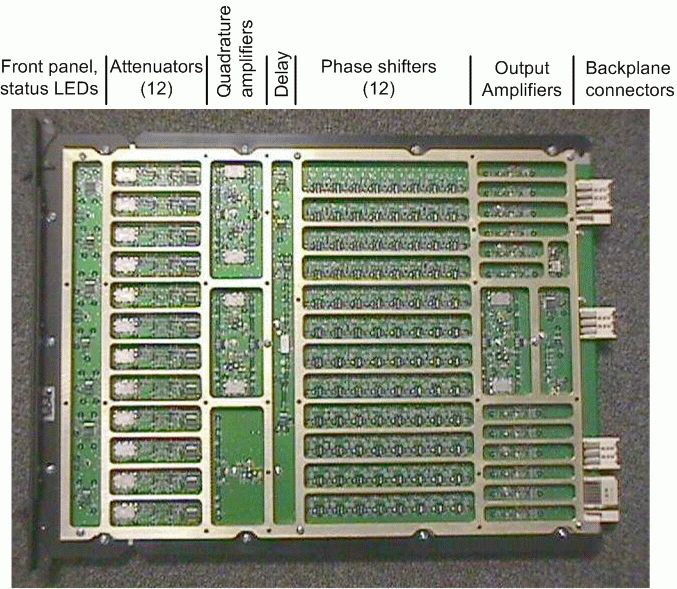
Metawave’s patented architecture included sectored antennas which replaced each of the traditional 120-degree antenna beams with four, 30-degree beams – for a total of twelve separate, simultaneous beams around each base station. In order to perform load-balancing, the appliqué was designed to resize each of the original sectors so that an overloaded sector, e.g. Alpha, could be decreased is size (becomes a smaller “piece of the pie”), while the other two sectors were increased in angular coverage. This required a transmit (Tx) beam-former which provided separate parallel signal paths for each of the 12 beams. The beam-former had to be able to assign the Tx signal from any of the three original base station radios to any of the twelve signal paths while also being able to control phase and power of each signal path. The beam former also had to maintain very high linearity requirements, phase and attenuation accuracy.
Block Diagram

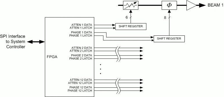
Special features to note in this design are a selectable delay line and the variable attenuators and phase shifters. The delay line was a requirement to account for fading effects caused by the physical separation between the three sectored antennas on top of the base station antenna mast. Switching the delay in an out of two of the three sectors accounted the fading between any combinations of the three. The variable attenuator needed to achieve up to 32dB of attenuation in 1dB steps, while the phase shifter was required to accurately control the phase to within 2.8 degrees (128 discrete steps) – in order to allow the original Alpha, Beta and Gamma sectors to be enlarged up to 11 beams, or down to a single beam for load balancing.

The digital portion of the Tx beam former wasn’t necessarily complicated but had to provided an extremely large number of discrete control lines. This was complicated by the state of the art for RF devices such as the attenuators. Unlike today, where a discrete-step attenuator may be controlled by a three-wire serial interface, devices at the time required unique parallel control lines for each bit. Board-level and Systems Specifications
The functionality of the load-balancing system forced a very high level of RF functional performance at the board level, including the Tx beam former. I was involved early on in the system architecture and performance definition in order to ensure specifications were not unrealistic. This had a very positive effect on design risk, resulting in first-pass success of the Tx beam former design, and high yield in early production.
Hardware Design
The hardware design was a fairly straightforward execution of a mixed-signal and controlled impedance RF circuit board. The sheer quantity of RF and digital nets however, drove this to be a 14-layer, double-sided design with both microstrip and stripline RF traces. The component count was over 2,000. Careful attention was paid to layout in order to ensure isolation between adjacent beams in the attenuator/phase shifter sections, thus driving shielding among other features. One result of the design was a patent award for a multilayer, linear phase shifter with excellent resolution and monotonicity (US 6,356,166 B1).

1. Input and output return loss 2. Gain and gain flatness over temperature 3. Phase accuracy, resolution and monotonicity over temperature 4. Attenuation accuracy, resolution and monotonicity over temperature Labview (National Instruments) was used to develop and automate the tests since the volume of data and the level of control (both PCBA and instrumentation) was far too extensive to be done manually. The program developed for this effort became the platform for production test.
Design Verification
Validation of the design was done by testing the following against the specification.
Staffing
I was the lead engineer for this design. I had support from a digital engineer who designed the FPGA program, from a test engineer who wrote the Labview program. I also worked with a lead systems engineer to develop the Tx beamformer specifications, and another engineer who designed the backplane – to which the beamformer interfaced.
